TDJ3M Views & sketching
In a non-perspective drawing there are no vanishing points therefore lines that disappear into the distance have to be treated in one of two ways - a) they don't exist (an orthographic or elevation) or b) they exist, but no perspective will be applied to them (oblique and isometric view). We create these orthographic drawings because you can take a designed part, draw it, dimension it and then give all the needed information to the manufacturer.
In a 3D environment dimensions become burdensome.
The following diagram is a sample of the typical reference material you might expect to receive on a technical illustration project. Most major plans after being designed will be broken down into elevation views (top view, front view and right view) built to make an isometric projection (image at upper right) to be given to the people in charge of manufacturing the product.
Technically an Orthographic view is simply the 3 elevations combined into a page and spread so that the top, front and side views are positioned to easily convert them into an oblique or isometric view.
One face is flat, the angle of the Z axis is then 45 degrees off of this.
The front and Z axis are both 30 degrees to the horizon.
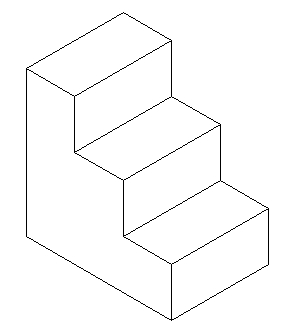
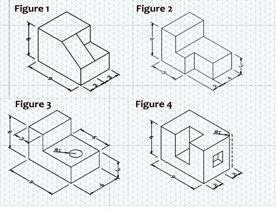
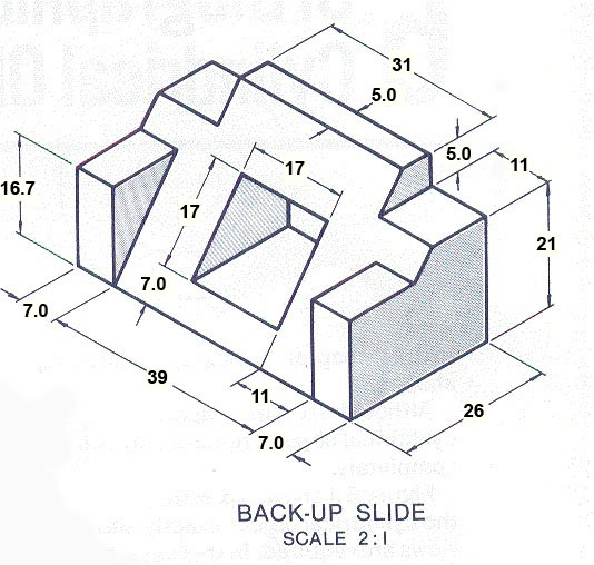
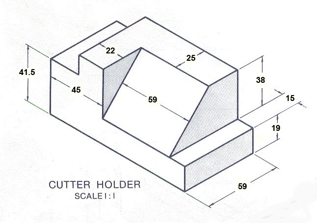
Convert the following into orthographic front, RS, top views. [trick - ensure that the maximum height is maintained as well as the edges]
|
CATEGORY |
4 |
3 |
2 |
1 |
||||
|
Orthographic projection |
Lines meet seamlessly. There are no flaws in the drawing. All elevations line up perfectly |
Lines meet at the edges with few flaws in the drawing. Some alignment issues. |
Lines generally meet at the edges. |
Lines meet but with much room for improvement. |
||||
|
Use of Time |
Used time well during each class period (as shown by observation by teacher, and documentation of progress in journal) with no reminders. |
Used time well during most class periods (as shown by observation by teacher, and documentation of progress in journal) with no reminders. |
Used time well (as shown by observation by teacher and documentation of progress in journal), but required reminders on one or more occasions to do so. |
Used time poorly (as shown by observation by teacher and/or documentation of progress in journal) in spite of several reminders to do so. |
||||
|
Filetype and size |
All elements are present. |
|
|
Only a few of the requirements have been met |
A thorough understanding of the principles of 1-Point and 2-Point Perspective is essential to creating an accurate, and visually appealing piece of art. A lay-person with no technical understanding of the principles of perspective
drawing will nonetheless have an intuitive negative reaction to a piece of art in which something is amiss. Using the perspective techniques shown in the preceding tutorials, the mental impression they will make on a viewer will be so strong that once mastered, the illusion of 3-dimensional depth will remain, even when the visual trickery involved in the process has been revealed.
Any good technical illustration starts with well executed line art. If you are working from any type of reference other than a CAD output in the desired angle, you will need to have a strong fundamental understanding of the principles of perspective drawing. This page will cover the various types of perspective angles you will encounter. In the tutorial lessons that follow this page, you will be given the tools needed to map out a perspective grid for any
s-dimensional situation. From this grid, you will be able to create realistic three dimensional drawings from flat or "Off Angle" reference.
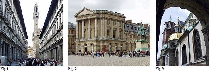
The three photos below demonstrate the difference between 1-Point and 2-Point Perspective, as well as 3-Point Perspective. The first photograph (Fig. 1) is an example of one-point perspective. All of the major Vanishing Points for the buildings in the foreground of Fig. 1 converge at one central location on the horizon line. The angle of view or Point Of View (POV) in Fig. 1 is referred to as Normal View perspective. In Fig. 2 the vanishing points for the two opposing faces of the center foreground building project towards two different vanishing points on the horizon line. In Fig. 3 we see that the horizontal building elements project to the left and right horizon and the vertical building elements project to a central vanishing point in the sky. This upper vanishing point is called the Zenith. If one were looking down on the object from a Bird's Eye perspective, the vanishing point below the horizon and would be called the Nadir.
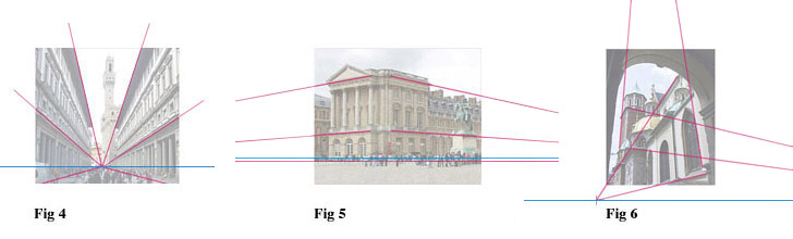
In the next three diagrams, you will see the same three photographs with Vanishing Point trajectory lines (magenta) and Horizon Lines
(blue) traced over the subject matter. Fig. 4 and Fig. 5 are both examples of Normal View perspective. A Normal View angle places the Horizon Line at a
natural height as if the viewer was looking straight forward without tilting the head/camera up or down. In these two examples, you will notice that all of the vertical features of the buildings are straight up and down.
Fig. 6 is an example of a Worm's Eye perspective. In Fig. 6 the head/camera is tilted upward placing the Horizon below the picture. The perspective when the view is tilted in an upward direction, creates a third vanishing point at the Zenith. All of the vertical building features will converge at this upper vanishing point. If we were looking down on a subject, the viewing angle would be a Bird's Eye View and the vertical details would converge at the Nadir.